Rotor School
Design and Materials
There are approximately a dozen domestic impact crusher manufacturers, and a few from Europe and Japan, offering both primary and secondary impactors. Rotors in domestic impactors vary from 36″ to 72″ in diameter, with hammer lengths from 30″ to 72″. Foreign impactors are typically larger in diameter and have greater hammer length, up to 86″ in diameter and 120″ in length. Rotors also vary in the number of rows of hammers.
Domestic primary impactors have either 2 or 3 rows, while imports have 4 or 6 rows. Secondary rotors tend to have more rows of hammers than primary rotors do. Domestic primary rotors are all made up of solid body construction. They are either a one-piece casting or they are manufactured from steel plate in a stacked disc configuration, with the discs welded together.
What is the advantage of one versus the other? A sound, one-piece casting seems to be preferable, but the emphasis is on sound. Casting inclusions, or shrinkage faults, in pieces weighing up to 20,000 pounds are not uncommon. These faults can only be detected by X-ray examination. If found, they are usually difficult, or impossible, to repair. Stacked and welded disc rotors are easier to manufacture. With proper material quality control and careful manufacturing techniques, stacked and welded disc rotors are every bit as good as a sound casting.
Shafts
The two things that fail most often in impactors are the bearings and the shaft. Proper material selection and proper shaft design go a long way in avoiding failures. In almost all domestic impactors, we find shaft designs handed down from pre-World War II standards. For instance, almost all shafts are shrink fitted or pressed into the rotor body and keyed. These keyways in the shafts extend right to the end of the rotor body. By doing this, tremendous stress risers are created at the point of the greatest shaft loading and stress.
Another example of promoting shaft failure is the practice of mounting tapered or straight bore bearings by means of shaft threads, locknuts, and lock washers. This also requires that a keyway be cut into the shaft, again creating stress risers at this critical shaft section.
Hammer Mounting
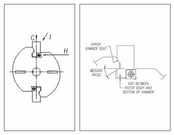
Hammers in OEM rotors are secured in a variety of ways. Some are good, some are average, and some are bad. All methods use some sort of wedging system, which presses the hammers into a seat in the rotor slot. Most OEM designs also incorporate bolts through the hammer and the rotor body. Having positive seating surfaces, for the hammers, in the rotor slots is what separates the good designs from the bad. Let’s examine the forces exerted on the hammers and on the rotor bodies.
Centrifugal Force C
Assume that a rotor has a 50″ diameter tip circle, that the rotor is turning at 500 rpm, that the center of gravity of the hammer is 19″ from the center of the shaft, and that the hammer weighs 800 pounds. This hammer develops a centrifugal force of 108,000 pounds.
Impact forces I
Under the previous assumptions, The hammer has a tip speed of 6540 feet per minute, or 109 feet per second. Now assume a 36″x 36″x 36″ rock falls from the inlet of the crusher a distance of 5 feet, before hitting the hammer. This rock weighs 4,000 pounds and develops 20,000 foot-pounds of Kinetic Energy. After hitting the hammer, the rock either breaks or its motion is stopped by the hammer, reversed, and thrown up against the breaker rolls or curtains inside the crusher housing.
Assuming the rock is stopped and reversed within 3″ of hammer travel, the force of the blow, or impact force I, would be 80,000 pounds. A 48″ x 48″ x 48″ rock, under the same conditions, would create an impact force of 192,000 pounds. As Force I acts at a certain angle from the centerline of the hammer, its vertical force component will be smaller than I, but can approach, or exceed, the centrifugal force C.
Wedging Force H
This force, H, varies greatly from one OEM design to another, and depends upon the angle of the wedging surface. Take this example as a poor means of hammer seating. With a 13 degree wedging angle, the horizontal wedging force comes to 480,000 pounds, based solely on the previous 108,000 pound centrifugal force calculated above.
When analyzing the forces C, I, and H, we can conclude that serious cyclical loading on the hammer and rotor slot occurs. Centrifugal force is always present when the rotor is turning, as is force H. When large rock is fed into the crusher, it will reduce C and H, or even overcome them momentarily. With hammer tips passing by 17 times per second, millions of loading cycles will occur in one week of crushing.
It is critical that the upper hammer seat provide optimum absorption of the impact forces. It is also critical that the lower hammer seat has a generous wedging angle. Finally, the hammer must be able to bottom out in the rotor slot when downward impact load overcomes centrifugal force. Unfortunately some, or all, of these criteria are not met by many OEM hammer mounting systems.